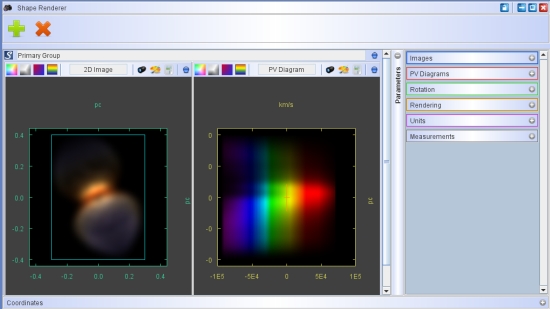
In the rendering module you will see and control the imaging output, as well as position-velocity diagrams and channel maps. Here you can directly compare your results with observations by overlaying observed images, p-v diagrams or channel maps. For simplicity, below we shall include p-v diagrams and channel maps in the term "images", since they are also two-dimensional sets of information and are actually displayed as images.
The rendering module consists of sections for the image display, tool bars for the control of the image type and appearance, as well as a parameter panel from where to control rendering, seeing and velocity resolution, spectrograph slit properties, camera rotation, and other parameters.
The image view can have more than one image-pv display simultaneously. This allows to render several camera views or spectrograph slit positions simultaneously and compare them to their respective observations. To add or remove use the green "+" and the red "x" buttons respectively.

To change the parameters separately for each display activate the display by clicking anywhere inside its area (a thin green border appears). Then change the parameters.
You can render all the displays at once by clicking on the large "Shape" button at the top of the Desktop. Individual displays can be rendered using the small blue "S" button in the top left corner of each display.

Each display has a title, which can be edited by the user for better identifying its context. In rendering and saving animated sequences of images, this name is used to label the images in addition to identifiers of their type and sequence number. To the left of the title are four buttons that you will use to select the type of image that is displayed. These include the "color", "greyscale", "red-blue" Doppler and "rainbow" Doppler image. The rainbow Doppler image is also used to show the colors that result from the spectrum of an object that has been rendered with physical radiation transfer.

To the right of the image title there is a number of buttons that allow you to load a background image (lens icon), change the image scaling (color palette), the display properties (calculator icon) and several operations to save your results in non-default files (blue marble).
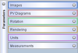
Initially the parameter panel to the right of the image displays is closed. When you open it by clicking on the "-" icon, additional tabs appear. Open these tabs gives access to a variety of parameters that control the output of each display. These tabs include "Images" where you change the parameters for the image dimensions, spectrograph slit and image convolution with the seeing point-spread-function. Similarly, the "PV Diagrams" tab contains the parameters for the position-velocity diagrams like their extend in velocity space and resolution. The "Channel Maps" tab lets you select the parameters for the different channels, the display table and whether to use the "Lightecho" mode. The "Rotation" tab includes the camera view point, i.e. rotation, parameters. The "Rendering" tab allows you to choose from several rendering algorithms and set their detailed characteristics. Here you can also set image modifiers designed to apply filters during the rendering step. For instance, this is equivalent to using color filters before the light reaches the detector. From the "Units" tab you can set the distance, physical images scale and the conversion between the physical image scale and generic rendering scale that is used for the model in the 3D Module. Finally, the "Measurements" tab can display a protractor that is useful to measure distances and angles within the rendered model image or observed background image in the image display.
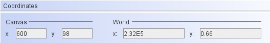
At the bottom of the Rendering Module there is a "Coordinates" panel which displays the cursor coordinates in terms of images canvas pixels as well as physical world space coordinates. The coordinates panel is closed by default and you can open it by clicking on the "+" icon in the lower right corner of the Rendering Module.